on
How Libcorrect Corrects Errors, Part I
Libcorrect is a BSD-licensed library for forward error correction. What this means is that it can be given a payload of data and apply specially chosen redundancy. The payload and redundancy are transmitted together and then sent along a medium that might add errors. Once received, the entire structure is decoded into the original payload. The redundancy allows libcorrect to decode the payload as long as the added errors do not exceed some limit. Because it is BSD-licensed, libcorrect can be used for personal and commercial applications.
This blog post is the first in a series which will explain how libcorrect works and what techniques it uses to decode more quickly. This information will hopefully help others who wish to learn more about FEC, implement their own error correction, or contribute to libcorrect. When I first set out to write this library, I had only a passing familiarity with each of these algorithms and managed to piece together some idea of how they worked. It took me quite a while to research each algorithm and my hope is that this post can help others shortcut past some of this time spent.
Libcorrect currently implements two kinds of error correction, convolutional codes and Reed-Solomon error correction. It uses the Viterbi algorithm to efficiently decode convolutional codes. Neither of these algorithms would be considered state of the art currently, but both were used extensively previously, with applications including dial-up modems, QR codes and long-range space communications. Convolutional codes are robust against Gaussian white noise – that is, transmission errors which occur randomly and according to a normal distribution. Reed-Solomon applies redundancy to a block of bytes and can repair errors that occur anywhere inside the block, even if all of the errors are contiguous to one another. Combining these techniques gives a powerful basis for transmitting in the presence of noise.
This post will focus on the fundamentals of convolutional codes and the Viterbi algorithm. Part II will examine the techniques used by libcorrect to accelerate convolutional code decoding, which includes both portable optimizations as well as Intel SSE vectorizations. Later posts will cover libcorrect’s use of Reed-Solomon error correction.
Convolutional Codes
There are a wide range of options available for forward error correction. For example, we might choose to take each bit of our message and repeat it 3 times. On the receiving end, we would examine each grouping of 3 bits and pick whichever bit appears in majority. We’d like a scheme that has good resilience to errors while not adding too much overhead to our transmission.
Convolutional codes offer a way to encode information about each bit of our message over multiple bits in the transmission. This method effectively “smears out” each bit with its neighboring bits so that no transmitted bit contains only information about just one message bit. The encoder pushes each bit through a shift register and then transmits the outputs of carefully chosen XOR operations. The decoder recreates the message by simulating possible message bits and measuring errors against the received transmission, then choosing the sequence of message bits with the least error. This method can recover the message even when the transmitted bits are received incorrectly periodically. The following sections will examine in more detail how this technique is implemented.
Shift Register
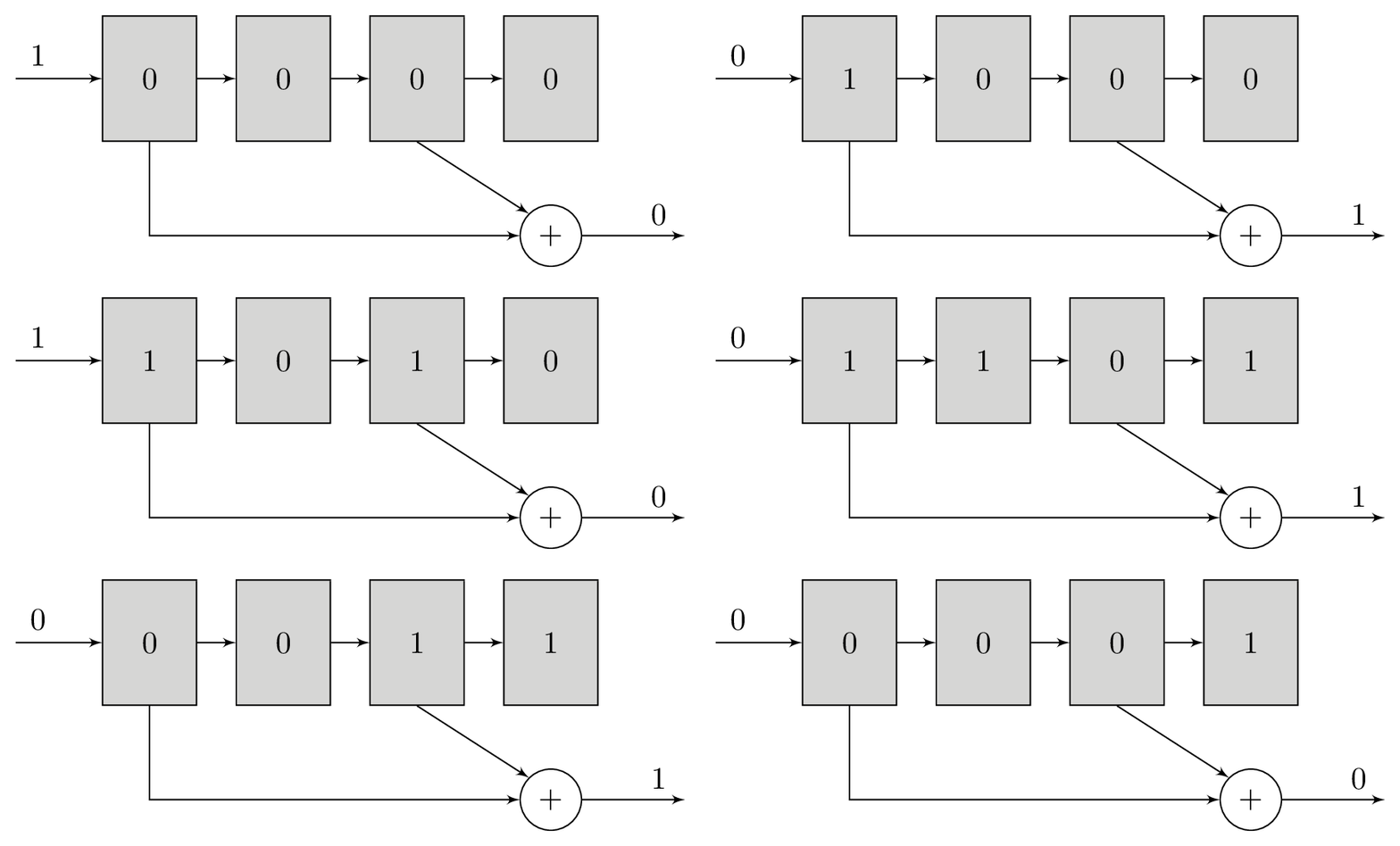
The shift register is a small piece of memory that can store k bits. It is called a shift register because we add a new bit to one end and each bit after slides down to the next cell. We only write one bit in at a time, but we read all the bits concatenated together. If a 4-bit shift register has the contents {0, 1, 0, 1}, we will write that as 0101. New bits shift in on the left hand side and are discarded on the right. This conceptual device is at the heart of the convolutional code algorithm.

Polynomials
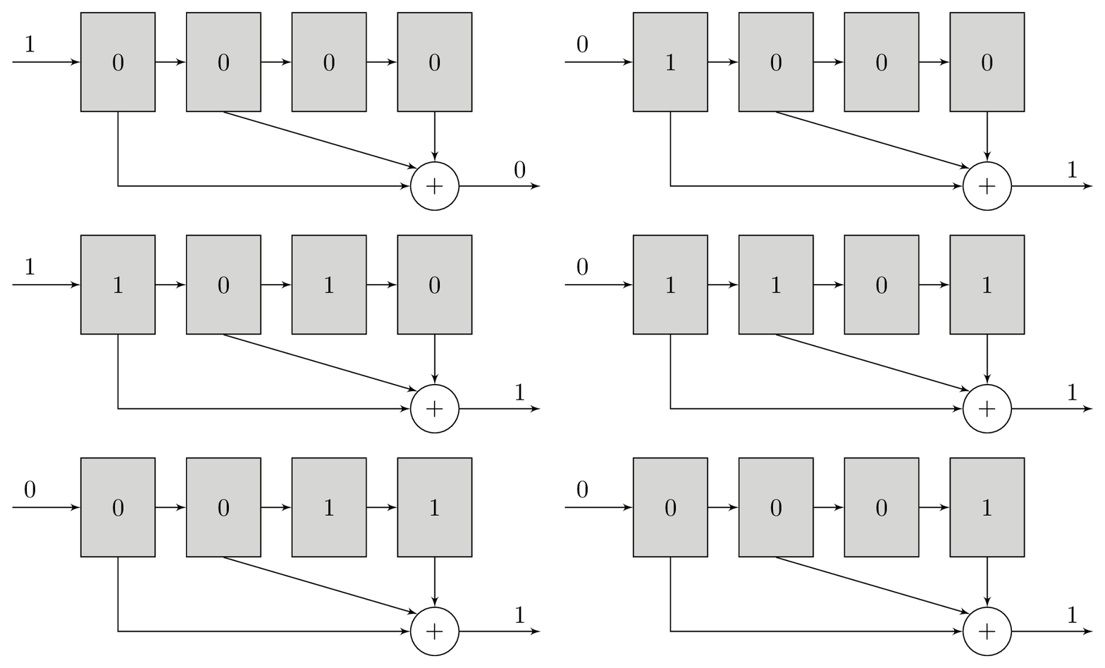
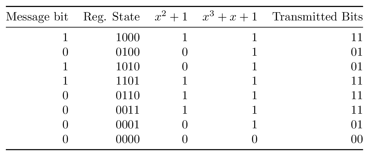
A polynomial is a series of bitwise XOR operations that computes a parity bit – the polynomial operates in GF(2). These polynomials will return 1 if an odd number of bits are set and 0 if an even number of bits are set. The polynomials are run with the contents of the shift register as their input. For example, the polynomial x2 + 1 computes the bitwise XOR of the third newest bit and newest bits in the shift register, while x3 + x + 1 would do bitwise XOR of the fourth, second, and first newest bits.


It is these polynomials that form the basis of our redundancy. For each bit that we will load into the shift register, we will transmit the output of at least two different polynomials. The original message itself is not transmitted. Using more than two polynomials can increase tolerance to noise, but comes at the cost of reducing transmission throughput. The polynomials are chosen carefully to complement each other and increase tolerance to noise.
Encoding
Encoding convolutional codes involves taking the message we want to send and feeding it one bit at a time through our shift register. The shift register will initially start with all zeros. Each time we feed in a new bit, we will save the output of each polynomial that we have chosen. We continue this process until the entire message has been fed into the shift register, followed by a sequence of 0s to flush the shift register. Once we have completed this process, we send the interleaved polynomial outputs. The transmitted message does not contain the bits of the original message.

Decoding
As described in the section on encoding, we’ve been given the outputs of the polynomials, not of the shift register itself. What we want to do is to work backwards from these polynomials to determine the most likely input bit to the shift register that produced the received bits. When the decoding algorithm has finished, we hope to recover the series of input bits that were used to generate the polynomial bits that we received.
At first glance this might seem impossible as there are many bits in the shift register but only 1 bit from each polynomial. The only way we can determine which input bit produced the polynomial bits is by simulating the shift register for each group of polynomial bits that we receive. We measure the error between the expected polynomial outputs for each shift register state and the polynomial bits that we received and accumulate the error for each group of inputs. This works well because the shift register’s current state is closely associated with its state at the previous bit. A shift register with the contents 1001000 will contain B100100 when the next bit B is shifted in.
Let’s use the example 4-bit shift register with polynomials x2 + 1 and x3 + x + 1 mentioned previously. Our approach for decoding will be this: simulate a 4-bit shift register with contents all zero as we started with in the encoder. Next we simulate the first unknown bit being shifted in, which gives us two new possible shift register states, 1000 and 0000.
For each of these two states, we will evaluate both polynomial outputs. We then compare these outputs to the two bits we actually received. For both shift register states, we measure the error between what we’d expect our polynomials to generate and what we actually received. Finally, we record this error total for each state. It might turn out at this point that one state mismatched on both polynomials while the other mismatched on neither, yielding error counts of 2 and 0, respectively.

We continue this process for every grouping of polynomial bits we receive. Every time we simulate new shift register states, we copy over the error total from the previous state. For example, if state 0000 had an error of 2, then in the next bit, states 0000 and 1000 will start with an error of 2. Once we’re out of bits to decode, we choose the sequence of bits which has the smallest accumulated error. This sequence is declared to be the original message.

This strategy has one major flaw. Every time we want to simulate another bit, we must store twice as many register states as we did in the previous bit. When we started, we needed only simulate 0000 and 1000. For the following bit, we needed to simulate 0000, 0100, 1000, and 1100. Once the sequence is longer than the shift register, we still must track all possible states, which means that for a message of length m we will need to track the error count for 2m states. This adds up quickly! Thankfully there is a clever trick which reduces the need to track so many states.
Viterbi Algorithm
The Viterbi algorithm is a Dynamic programming approach to decoding convolutional codes. This algorithm makes one important observation about the sequence of decoded bits. Once our sequence of bits is longer than the length of the shift register, we can discard unlikely paths. Rather than storing error information about 2m paths, we only need store m * 2k paths (for message length m and shift register length k).
Let’s return to our previous 4-bit shift register. Suppose that we are decoding and have received our 4th set of bits and have calculated all of the error counts for the received bits. We have 16 possible sequences so far, and the next set of bits received will bring us to 32 sequences. Each sequence will track 5 bits, but only 4 bits will actually be used for error calculation. If we carefully compare and select sequences at this step, we can actually eliminate half of the sequences without any loss in ability to decode the message.
Imagine that we have calculated the error for sequences 0110 and 0111. In the next step, the rightmost bit will shift out of the shift register and will no longer make any contribution to the error count, but we still need to keep track of it to know which bit was transmitted when we finish decoding. Both of these sequences will appear to shift to B011 in the next step, where B is the next bit transmitted. It turns out that we can simply discard whichever of these sequences has a larger error at this point and then record the rightmost bit from the “winning” sequence.

For every sequence at this step, there is a complementary sequence we can compare it to. Specifically, the sequences XYZ0 and XYZ1 will be compared and one chosen as a winner. We then store the rightmost bit of the sequence with the smaller error in a table. Once we have finished this step, we will have a table with one bit for each sequence of length k - 1. We will repeat this step for every new group of inputs. Libcorrect calls this table a “history table.”
Once we have finished decoding the message, we will actually work backwards to recover our message. We will start by inspecting which shift register state has the smallest total accumulated error and declare it to be our sequence. We will then shift this state backwards once and use this value to lookup the next bit in our history table. We will OR this bit back into the register and then shift again, repeating the process until we have rewound the entire history table.
You might be wondering whether we could simply choose the sequence with the smallest error amongst all sequences and store only that sequence, rather than storing an entire table. Although this is one possible strategy, it will not yield the same error correction robustness as storing all paths. If we encounter a short-lived burst of errors, it may adversely influence the error count for the correct sequence – remember that we are choosing the sequence which is most likely given the information we have. If we wait until the message has finished and then recover the bits, we are more likely to converge to the correct sequence.
In practice, it is common to do some hybrid approach. The table can store some multiple of k time shifts of sequences, with a periodic “rewind” operation clearing space for new sequences and decoding part of the message. For example, we might wait until we’ve decoded 20 * k groups of inputs, and then decode the oldest 15 * k bits, leaving the rest for more convergence. Letting the table grow larger uses more memory but requires less CPU time.
Demodulation
When we send data across a network, we usually think of it as being received as a binary signal. The final part of the receiver might be a program that gets bytes of data from a socket. At a lower level, for certain kinds of lossy networks, the data might actually be transmitted as an analog signal. This implies that some part of the receive chain has to convert the received signal back to a digital signal. This component could be the software defined radio on a wireless chipset or even an analog-to-digital sampler on a soundcard.
Often our receivers initially get this signal with some analog fidelity. The code that demodulates the signal can produce a ‘soft’ bit which encodes the demodulator’s confidence in the demodulation process. For example, the demodulator might produce an 8-bit confidence value for every single bit received, where 00000000 implies a high level of confidence in a 0 bit, 11111111 implies a high level of confidence in a 1 bit, and 10000000 implies complete uncertainty in which bit was received. This confidence value is useful during error correction because we will want to aggregate our decoding process over a long sequence of bits. Receiving a high level of uncertainty about a single incorrect bit from the demodulator helps the decoder make the right decisions for the other nearby bits.
Decoding Soft Bits
We can make use of the demodulator’s soft bits during the convolutional code decoder process. If we run this process on soft bits rather than hard bits, we can continue to recover the message in the presence of more noise than we would have been able to otherwise.
Decoding convolutional codes with soft bits is almost exactly the same process as with hard bits. Previously we calculated the error as the number of bits which differed between the received bits and the simulated polynomial outputs. With soft received bits, we will instead store the absolute value of the difference between the received soft value and the simulated polynomial value encoded as soft bits. For example, if the polynomial value is 1 and the received soft value is 1110000 then we store 11111111 - 11100000 = 11111 as the error. If instead the polynomial value were 0 and the received soft value were 10100000 then the error would be 10100000. The error continues to accumulate as a sum just as it does when decoding hard bits.
Configuration
We can get more error correction resilience from convolutional codes both by increasing the length of the shift register and by adding more polynomials. Increasing the length of the shift register does not reduce the transmission speed but does cost more CPU resources to decode. Every time we lengthen the shift register by one bit, we will reduce the decoding CPU performance by about 50%. Adding more polynomials adds transmission overhead but has less CPU impact than adding another bit to the shift register.
In practice, common lengths for the shift register range from 7 to 15 bits with 2 to 6 polynomials. Even a modern CPU cannot decode more than 1 million bits per second for a convolutional code with k = 15. These configurations were used for a wide range of error correction including communications with the Voyager probe and the Mars Pathfinder.
Stay tuned for the next post which will examine how libcorrect accelerates the convolutional code decoding process. If you have questions or comments about this post, stop by and say hello.