How It Works
Quiet Modem encodes your data into sound that can be played by your speakers. These sounds can then be detected through a microphone and converted back into data.
This section of the documentation is optional. It can be skipped if you just wish to begin using the modem. However, if you need to debug your modem, it can be helpful to understand how these libraries work.
Soundcard
In order to understand what it means to play sound, it helps to first demonstrate how your sounds work within your computer. When we want to represent a sound, we sample it at periodic intervals in time. Each sample is rounded to one of thousands of discrete intensity levels in a process known as Pulse-Code Modulation. We refer to the number of samples represented in a single second as the sample rate. The most common sample rate for digital audio is 44,100 Hz (samples per second). The sample rate applies both to sounds that we want to play and sounds that we are recording. The computer has a sound card or chip which is responsible for converting analog sounds to digital samples and vice versa.
Quiet Modem operates internally at the sample rate of 44,100 Hz. Each sample is generated as a 32-bit floating-point value between -1 and 1. In fact, Quiet can operate across any channel that can transmit these floating point numbers, though the degree of success will depend on how much the samples are distorted after they are transmitted.
Modulation
As described in the section on soundcards, we will be operating on individual samples of sound. We know that we will be sending and receiving individual samples, each of which can be assigned a single floating-point value. We also know that these values will eventually have to be played as analog electrical signals which excite sounds through a speaker. We will convert data to sample values through a process known as modulation.
Quiet Modem uses Liquid SDR to do the heavily lifting for its modulation tasks. This section is describing mostly how parts of Liquid work. The key points are repeated in this documentation so that users of Quiet should not have to rely too heavily on Liquid's documentation.
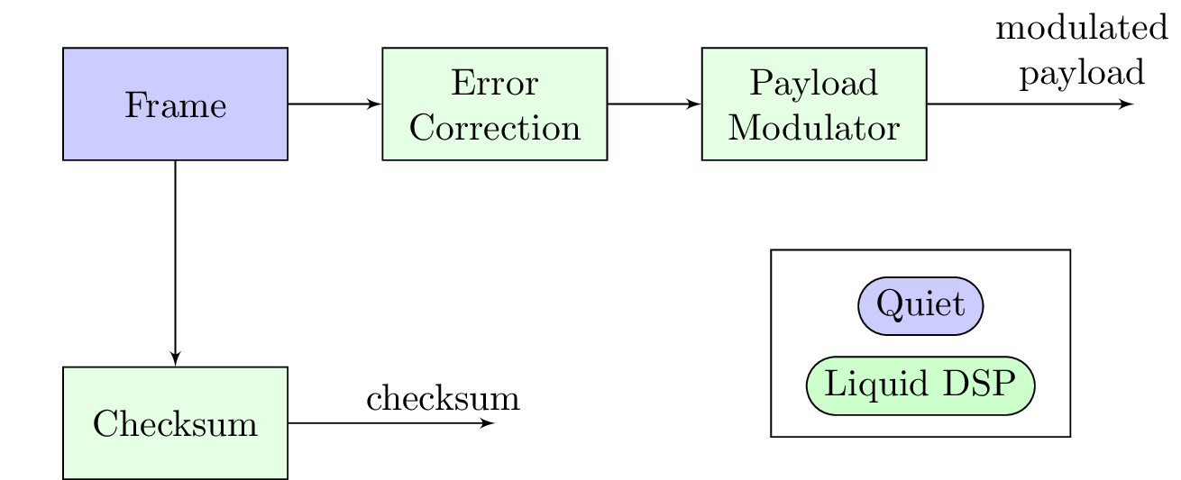
Framing
Quiet Modem sends data in chunks, which we will call frames. Each frame can be thought of as a completely self-contained packet of data. The start of each frame contains a synchronization sequence that allows the receiver to have a good chance of decoding the frame. Quiet performs checksumming on the contents of each frame so that it can discard frames that have picked up errors in transmission.
A single frame of data has a maxium payload size that it can carry. This size will depend on the specific configuration used, but in general, a frame will be converted into at most one or two seconds of sound. Frames that are longer than this are more likely to encounter errors.
It is up to the user of Quiet's libraries to split data into frames. Quiet will discard frames that are longer than the configured transmitter's maximum frame length. Although this is somewhat inconvenient, the upside is that frames are given back to the user in the same structure when received. This means that if you wish to use e.g. the first byte of each frame to signal when a message is starting or ending, you will always be able to find this marker at the first byte.
Checksum
Quiet offers automatic checksum verification of frames. The strongest of these methods offered is CRC32 which will fail nearly every time if even a single bit in the received frame is incorrect. Some applications may wish to disable checksums if receiving an incorrect message is preferable to receiving no message.
For this step, Quiet generates the checksum and then sets it aside for later. The checksum itself will be passed in a different part of the frame from where the user payload goes.
Error Correction
Before we modulate our frame, we can add redundancy to it. This redundancy allows the receiver to recover our original message even when some errors occur in transmission. This process is known as Forward Error Correction.
As an example, you can imagine that we repeat each bit of our message three times. Then when the receiver receives this message, it picks whichever bit occurs most often — if two of these three bits are '0' and one is '1', then we pick '0' as the original message bit.
Modern forward error correction is more sophisticated than simply repeating bits, but, as a consequence, not as easy to explain. Quiet Modem relies on the modes provided by Liquid SDR. In particular, it makes use of Convolutional Codes and Reed-Solomon. Once we apply these methods to our original message, we take the resulting bits and pass them on to our modulator.
Payload Modulator
Liquid SDR offers a wide range of modulation options, and so it is beyond the scope of this page to fully explain all of them. If you are curious which specific options Quiet provides, the documentation on Profiles offers more details. Quiet makes use of Liquid's standard modems, OFDM and GMSK modes. For this section, we will explore one of the most basic modes, BPSK.
In binary phase-shift keying, we assign each bit of the message we want to send into a sequence of floating-point samples. Each sample will represent a single bit of data. If we want to send a binary '0', then we create a new sample with a floating-point value of -1.0. If we instead want to send binary '1', then we assign the value of 1.0. Other modulation schemes can send more bits of data in each sample by picking more intermediate values, e.g. -0.5 and 0.5 and even complex values.
We now have floating-point samples where previously we had binary digits. If you were given the sequence created above, it would be easy to recover the original message. Unfortunately, we would not have much luck simply sending this sequence as it is. We will need to condition these samples so that they can deal with limitations in our real-world speaker. We will also need to make it easier for the receiver to find where our message starts.
Transmitting
Just as in our section on modulation, this section mostly describes functionality provided by Liquid DSP.
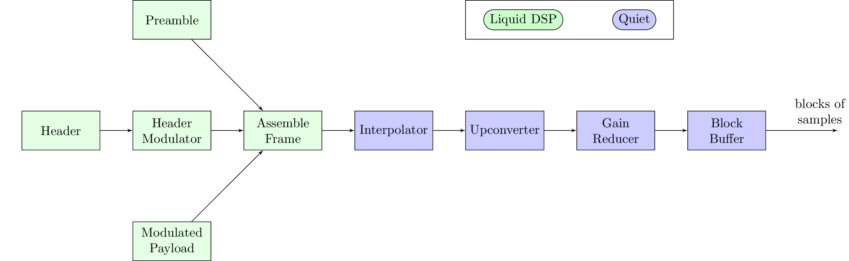
Preamble
Our receiver will be looking at a continuous stream of floating-point samples from the soundcard, waiting to see our message. These samples will contain all of the background noise near the microphone as well as whatever message we are sending. We need a way to tell the receiver that our message is about to begin so that it will know to interpret the samples it is seeing as message bits.
The way that we accomplish this is by using a predetermined, pseudorandom sequence of samples. We will start every message we send with this sequence so that the receiver will know unambiguously that our message is about to start. It will be much easier for the receiver to look for this specific sequence and then assume that the message follows immediately after. This sequence is known as the preamble. The preamble does not need to be modulated — the sequence itself is what we send.
Header
The header is a short block of data sent before the payload. The header contains information on which type of modulation and error correction are used in the payload. It also contains the actual checksum generated for the payload. A short checksum is sent for the contents of the header itself.
Header Modulator
Just as our message was modulated to floating-point samples, we will apply error correction and modulation to the data in the header. The kinds used here can be different from the one used for the payload. We want the header to be especially reliable since an error in the header can make it impossible to receive the payload correctly.
We do not send the type of modulation or error correction used for the header itself. These values are pre-shared and are part of the modem configuration.
Assembling the Frame
We now have all of the samples needed to send our frame. We start by sending the preamble samples, followed by the header samples, and finally the payload samples.
Interpolation
Interpolation is a process that allows us to restrict how quickly our signal changes values by inserting new 'fill' samples between each of our existing samples. We will fill in samples with values of 0 so that they do not change the overall energy in the signal. Next, all samples (original + fill) have their values smoothed out by evaluating a specially chosen polynomial that prefers slow changes in values over fast changes in values. In other words, we use a filter.
The new sequence of resulting samples will change less rapidly than the original, restricted to a narrower band of frequencies. The number of fill samples we choose allows us to control how much smaller the band gets. Inserting a single sample halves the range; inserting two reduces it to a third, and so on. Using a narrower frequency band will often give our data a better chance of being transmitted successfully. The downside is that it now takes us more samples to send the same message, which means our effective transmission speed is reduced.
We will apply this interpolation to the full contents of the frame, not just the part with our message.
Upconversion
Our interpolator reduced the bandwidth of our message, but the resulting waveform is very low frequency, centered at 0 Hz. Speakers do not work well at very low frequencies, so we will want to move our message out of that range through upconversion. Upconversion allows us to move the center of this transmission up to a new frequency, but with the same bandwidth as before upconversion.
For example, if our original transmission has a bandwidth of 4,000 Hz, and we upconvert it by 8,000 Hz, then it will sit at the range of 6,000 Hz to 10,000 Hz after upconversion.
This process is what allows us to go into the near-ultrasonic range. If we use interpolation to reduce our transmission be fairly narrow and then upconvert to 19kHz or so, the result will sit entirely above 18kHz, which is well above the hearing range for nearly everyone.
Gain Reduction
This step multiplies all values in the signal by some small fraction. This reduces the likelihood that the signal will clip beyond the acceptable range of [-1.0, 1.0], which our soundcard would reject. It also makes the transmission quieter so that it will be a reasonable volume regardless of how loud the user's volume settings are set to.
Block Buffer
We now have a stream of floating-point samples that is ready to be sent through the speaker. Soundcards expect to receive samples in blocks instead of one sample at a time. The soundcard's block length has to be preconfigured and some power of 2, commonly in the range of 256 (2^8) to 16384 (2^16). This step collects samples into bunches to match the soundcard's block length.
If too many samples are generated to fit into one block, Quiet sends one block's worth and stores the rest for the next block. If more samples are needed to fill a block, Quiet checks its send queue to see if more data frames are ready and fills with silence otherwise.
Receiving
The receiver is running on a separate device from the transmitter. Here we will take samples collected by our microphone and decode the transmitted message.
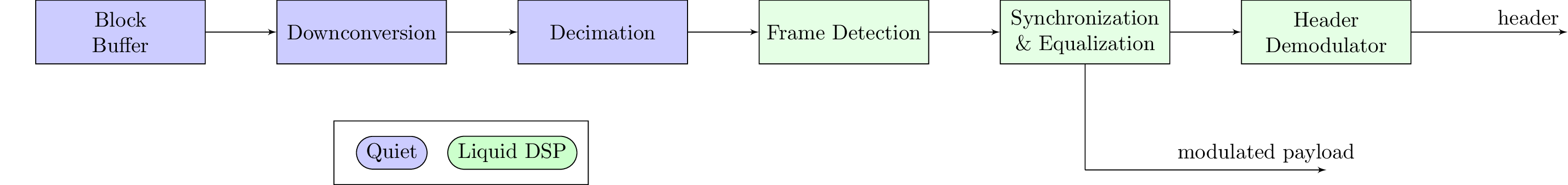
Block Buffer
The soundcard will have collected floating-point samples of sound recorded by the microphone. These samples are sent to us in blocks made of multiple samples, just as when we sent samples to the speaker. Each block's length is a some power of 2.
Our block buffer serves as a temporary store of samples as we run the decoding process.
Downconversion
We have to invert the upconversion process so that the original signal's center is shifted back down to 0 Hz. This should be matched to the transmitter so that we shift down by the same frequency interval that we shifted up.
Decimation
This step inverts interpolation. First we apply a low-pass filter to our signal and then we throw away samples. This should also be matched to the transmitter. For example, if we had chosen to interpolate by 2, now we will decimate by 2.
Frame Detection
The resulting stream of samples should now resemble what we transmitted. When we sent our frame, we started it with a preamble. Now we will search for the preamble in the incoming samples. This is an ongoing process and will continue to run as long as no preamble is found.
Synchronization and Equalization
The preamble is made up of a few different parts. The first part of the preamble is easily detectable so that we know where the frame begins. The next part of the preamble helps us synchronize our timing to the transmitter's timing in a precise way.
From the section on Payload Modulation, we described how we convert binary data into floating-point amplitudes. One of the challenges we face in decoding is deciding at which point it will be appropriate to read these floating-point samples. The preamble helps us accomplish this by giving us a predictable sequence to look for. Even if noise is present on top of the preamble, we can still achieve a pretty good synchronization by looking for successive samples.
We will also use the preamble to compensate for the uneven frequency response of the transmit and receive channel. It is typical that our transmission channel will emphasize certain frequencies and attenuate others. We use the preamble to invert this bias introduced by the channel so that the signal we receive looks nearly flat again.
Demodulate Header
With our clock aligned to the transmitter's, we are ready to begin decoding data. We start by decoding the modulated header samples. This data includes checksums of the payload and the header itself, as well as the type of modulation and error correection used in the payload. If the checksum of the decoded header data matches the checksum sent with the header, then we proceed to decoding the payload.
Demodulation

Demodulation
Using the demodulation method specified by the header, we now demodulate all of the frame's payload samples. We perform soft demodulation so that the samples are demodulated into 8-bit "soft" bits. That is, for each bit of data transmitted, we now have an 8-bit value that reflects our belief about what might have been transmitted. A soft bit of 0 means that we are highly confident that a 0 was transmitted, 255 means that we are highly confident that a 1 was transmitted, and intermediate values mean we have some level of uncertainty. A value of 128 means that we believe either bit was equally likely. Preserving this level of uncertainty will help us during the error correction phase, as bits with lower confidence will accumulate less error.
To use our BPSK example from the modulation section, where we transmitted -1.0 for '0' and 1.0 for '1', imagine that we receive the sequence [0.9, -0.95, 0.1, 0.9]. If we were to decode these back to single bits, then we would decode this sequence as [1, 0, 1, 1]. However, if we use soft bits, we get [242, 6, 140, 242]. This better captures our uncertainty about the '0.1' sample we received, which is nearly as likely to be '0' as it is '1'.
Error Correction
Now that we have the soft bits demodulated, our next step will be to apply the error correction techniques for the redundancy we added during modulation. The error correction will need to be good enough to decode the samples in spite of other noise occuring. Even the signal itself becomes noise, as echoes of the signal are picked up by the microphone.
Data Integrity
Finally, we take the checksum value stored in the header and compare to a checksum of the data recovered after error correction. If these checksums match, we can be relatively confident that we have received the transmitted message. The bits can now be passed to the user.
The checksum stage is optional. Some applications may be well suited to receive messages with some errors. It is up to the user of Quiet Modem to decide whether to checksums should be used.
Thread Safety
The Quiet Modem library has some features that help it work well in a multithreaded environment. In particular, Quiet assumes that the interface to the soundcard will run on a different thread than the user application. Quiet attempts to decouple its functionality so that it can be used in a threadsafe way.
Ring Buffer
One of the key components of Quiet's threadsafety is a ring buffer that allows safe communication between threads. Quiet's ring buffer allows any number of readers and any number of writers. If the buffer is empty or full, it has mechanisms to allow readers and writers to block until data or space in the buffer is available.
In general, we try to keep frames of data in buffers, rather than modulated samples. This is because a modulated frame uses much more memory than the demodulated payload data.
Send Queue
On the transmit side of Quiet, we use a ringbuffer to build a send queue. This allows senders to queue up packets for transmission as capacity allows. When the soundcard is ready for more samples, Quiet can read from the send queue and modulate one or more frames to fill up the soundcard buffer as necessary.
Receive Queue
On the receive side of Quiet, we have a receive queue. Samples are continuously read from the microphone into Quiet's decoder. When it has successfully decoded a packet, the packet's payload is written as a complete frame into the receive queue. Users of Quiet can perform a blocking read of this queue which will wait until a frame is ready.